Background
(1) System of Systems
The concept of “system of systems (SoS)” appeared in 1950s, and nowadays it is common to see the SoS concept in different domains. However, there is no standard definition for SoS. There are lots of perspectives from various fields of studies about an SoS. Eisner defined SoS as large, geographically distributed assemblages of systems. The component systems and their integration are deliberate, and centrally planned for a particular purpose. Shenhar stated SoS as a large, widespread collection or network of systems with functioning together to achieve a common purpose. He also described SoS as an array of systems. Maier described SoS as a set of collaboratively integrated systems, and the systems hold two main properties: operational independence and managerial independence of the components. Krygiel suggested that an SoS is a set of different systems so connected or related together to achieve the goal which is not possible by individual system. Jamshidi stated SoS as a large-scaled integrated system which is heterogeneous and independently operable and the systems are connected through the network for the common goal.
(2) Chaos Engineering
The evolution of large-scale distributed software systems is causing a major change in software engineering. The industry of IT is quickly adopting a way to increase development flexibility and deployment speed. Even if each individual system or service within the distributed system behaves correctly, interactions and collaborations among the services can have unpredictable results. In other words, if an unexpected result occurs due to the very rare but destructive real-world impairment which directly affects the environment of the production, the distributed system becomes “Chaos”. Chaos engineering is an approach for learning the systems behavior by applying an empirical experiment in production. In order to apply an empirical experiment, we have to sample stimuli from the space of all possible events that might occur in the realworld. Stimuli are input for the empirical experiment and by injecting the stimuli, we can learn the behaviors of the system. The following are principles of chaos engineering.
- Hypothesize about steady state.
- Vary real-world events.
- Run experiments in production.
- Automate experiments to run continuously.
- Minimize blast radius.
Dynamic SIMVA-SoS
We use discrete time multi-agent simulation. Because it is discrete time simulation, the system updates for every time frame. We can control any number of injected stimuli for any time. In addition, it is easy to express the individual behaviors by focusing only the CSs as it is multi-agent simulation. This simulation structure is appropriate to represent the evolutionary development, which is one of the important SoS characteristic. To apply the chaos engineering idea into the simulation, the stimuli should be executed during the simulation. In discrete time multi-agent simulation structure, the system changes once per discrete time frame. Therefore, stimuli having a parameter for start frame value, we can inject the stimuli for dynamic simulation. For the stimuli injection, we proposed five injection techniques: value injection, tile injection, message injection, entity injection, and state injection. These techniques are derived from identified infrastructure and environment factors, and defined stimulus types. The first technique is value injection. This technique modify the stimulus type value while executing the simulation. For this purpose, we use Reflection Java API. Reflection allows us to access the methods, types, and variables of a class, even if we do not know the specific class type. In other words, it is possible to change the value of the variable at the corresponding point in the simulation using the Reflection. The stimulus type values that can be modified by the Reflection includes speed and the sight range, and communication range. The second technique is tile injection. This technique modify the stimulus type value based on the information contained in the tile of the map. Speed, sight range, and communication range need to be modified accordingly and proportionally as the map information dictates. We set a constant value on the range of the tile on the map. When the entity is within that tile, the stimulus type value is multiplied with a constant value.
This constant value is a representation of environment factors which affect the stimulus type value. The third technique is message injection. Differently with other stimulus type, communication does not contain the stimulus type value. Instead, simulation uses message router for communication. The message router decides for the delay or loss of a message by comparing the information of simulation time frame and message. If the message router stores the message, it represents the communication delay. When the message router deletes the message, it represents the communication loss. The fourth technique is entity injection. This technique adds or removes entities using a special function call. This function call is an initialization function call during the simulation execution. In the function call, it adds new entity containing initial value or removing information of entity. An entity represents a CS in the simulation. The last injecting technique is state injection. The state of the entity can be as-is or changed. The state of the entity is changed when the environment impairs the normal operation of the entity. For example, when the firefighter got injured, the state of the firefighter is changed to patient. For example, Fig. 3 shows the execution for firefighter’s speed stimulus type by using a value injection technique. The stimulus is injected at the initial phase. After initial phase, system updates every frame for simulation. At every update, the system checks the stimulus execution conditions. If the result of the condition are true, the system executes the stimulus. After executing the stimulus, the system stores the current stimulus type value into memory. Then, the system removes the executed stimulus to prevent the execution duplication. The impact of the stimulus is reflected in the firefighter’s movement method.
- Simulation
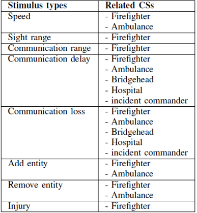
Defined stimuli along with related CSs
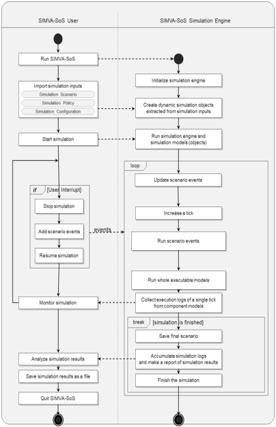
Workflow of Dynamic SIMVA-SoS
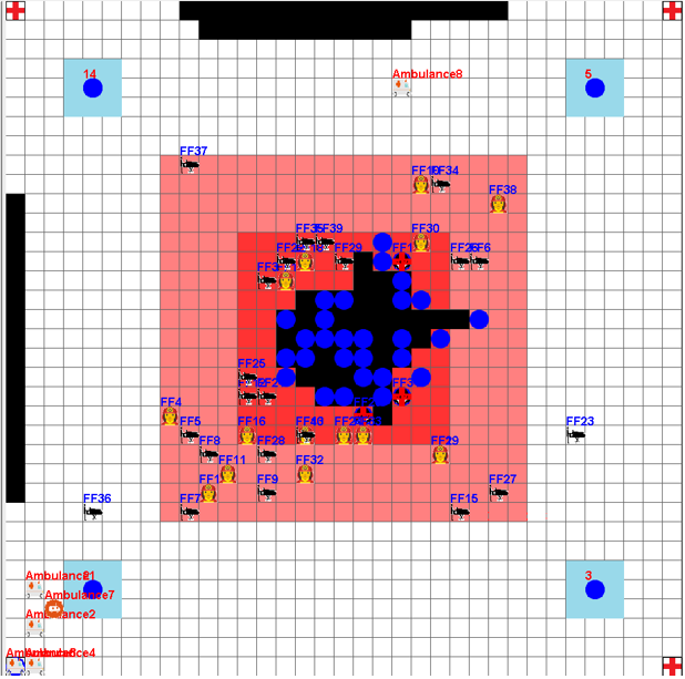
Dynamic SIMVA-SoS execution screen
-
Verification
- SIMVA-SoS verifies the input models by adopting SPRT algorithm.
- A SPRT algorithm is the fastest statistical model checking algorithm.
- In SPRT algorithm, SIMVA-SoS simulates the input models several times to each probability (from 0.01 to 1.00) for checking whether each probability is true or false.
- SIMVA-SoS can apply a specific verification property as a verifiable goal of SoS.
- There are 22 verification properties that we found from other existing research (listed in Appendix A).
- SIMVA-SoS shows the raw and analyzed result to the user.
- The raw result of the verification is the number of samples, number of true samples, the true/false tag selected by the SPRT algorithm.
- SIMVA-SoS provides the analyzed result to the user by the form of the graph for each probability and its specific value.
- SIMVA-SoS can save the results of verification as a file.
- SIMVA-SoS verifies the input models by adopting SPRT algorithm.
Open-source Repository
Github link: https://github.com/sumin0407/SoS-simulation-engine


